Find Rob on Google+
Mon
6
Apr

2009

Fitted new reduction style starter motor from late model C4’s – much lighter, easier on the battery and leaves more room for header exhaust pipes.

Fitted new Brake Master Cylinder, with brake bias spring.

Fitted four new Nexen tyres 275x40xZR17

Fitted New rear Disc Pads

New oil and oil filter

All four wheels aligned

Cleaned handbrake lever that was gunked up and fitted New Handbrake cable

New windscreen, frame blasted to bare metal and re sealed. New weatherstrip. New wiper blades. Windscreen coated with rainX.  http://robhealey.com.au/Corvette/tech-tips/windscreenwindshield-weatherstrip-replacement/

back to top

Mon
29
Dec

2008

May – replaced front disc pads with Brembo ones,(FM-1000m 0412). The EBC pads were hardly worn, but they only worked when extremely hot and were very poor when cold. The Bembro’s made a big difference.

July – Replaced all six universal joints. Although 5 of the old UJ’s looked OK, there was a noticeable difference with the new ones, and the car felt better, tighter.

Fitted new Monroe Sensatrac rear shock absorbers. I spent some time at the Corvette Forum, researching a good but soft shock absorber. The advice I got was excellent. Will upgrade the front shock absorbers too.

New Polyurethane rear suspension, well greased.

August – Fitted new waterpump, Flow Kooler 1688 from Summit Racing– 30% more flow up to 3500rpm.

Replaced the rear MAF relay because the warning light came on, this instantly fixed the problem.

Fitted quick fill fuel cap and two small louvres in tops of doors.

Fitted new Bosch style Altenator

Fitted New Internal Electric Fuel Pump.  I foiund a Holden one that was identical including the plug. Hi Pressure in tank for VN VS Commodore 6-8cyl. Repco # FPE-250A 

back to top

Mon
10
Nov

How to replace UJ’s WITHOUT removing C Beam

The factory service manual states that the C Beam must be removed to replace the universal joints on the propellor shaft. Some members of the Corvette Forum said that this was true, BUT a few said it was possible to do it and NOT disturb the C Beam – possibly this only applies to Auto trans like mine?

After some research I got confirmation from forum member rodj and some clear instructions on how to do this. The advantages of not removing the C beam is that it reduces the time of the job, possibly by a few hours! and there is no chance that the C beam will not be put back properly, nuts not tight enough etc because it is a well known PITA to work with due to lack of room – it has to be wrangled in and out and also very hard to get at the front nuts which are above the beam.
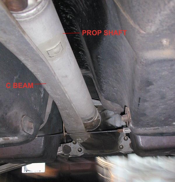
c-beam

The first part of this info concentrates on the prop shaft UJ’s, and then scorp508 has given permission for me to host his excellent write up on replacing the halfshaft UJ’s

Below is a copy of my write up for the mechanic who did the job for me, and after that scorp508’s tech tip with photo’s. The mechanic reported that my FAQ sheet was a huge help to him and confirmed that everything was correct.

NOTE – Driveshaft and halfshafts are made from soft aluminium and easily damaged.

All nuts/bolts are Metric.

Factory Manual and Haynes Manual supplied

Hood release under LEFT HAND side of dash,

This fact sheet is compiled from info received from other Corvette owners who have done the U/J replacement job themselves and is vouched for by several owners who have followed these or similar instructions.

The manual says to remove the Driveline Support Beam (C Beam) but this is NOT RECOMMENDED – all reports say this is a tricky job

“The C beam is a PITA to remove if you have never seen one before. You need small hands to get up side of tunnel and hold open ender on top of beam while undoing bolts underneath.Then you have to get it out which is a work of art in itself. Replacement also involves measuring alignement, R/R just for the C beam can take hours.”

The instructions for Driveshaft removal came from Rod in Sydney who has done the job many times and it can come out in as little as 10 mins.

REMOVE DRIVESHAFT FIRST so that brakes can lock diff to allow easy undoing of rear UJ Straps on diff.

Mark the drive shaft so you can install it back in the same position to keep the correct balance.

DRIVE SHAFT REMOVAL –

Hoist Car

Drop exhaust

Undo bolts holding uni to diff,  You may need the diff locked in order to crack the strap bolts loose , you can only really work on one bolt at a time and then need to rotate.

Use a long 1/4 drive ext for better access

MANIPULATE DRIVESHAFT OUT –

Driveshaft will  move foward on the trans yoke allowing you to get rear uni’s caps off the diff yoke. Need trans out of gear and handbrake off so you can rotate yoke to best position to get caps out .

Take rubber hammer, and tap the drive shaft FORWARD into the transmission, angle the drive shaft so its above the handbrake cable that goes horizontally across the car.

Take the rubber hammer, and tap the drive shaft out of the transmission.

DS will slide back beside diff head over handbrake cable enough for the  yoke to come free from trans.

The handbrake cable can be undone if needed, but I don’t recommend it because it’s 20 years old and may be brittle and break. (It’s made to come apart at the clip about in the middle)

May wish to have a catch pan under the rear of the tailshaft to keep transmission fluid from leaking on your shop floor

DS can then be moved foward to clear handbrake cable and down.

Check rear trans seal while you have DS out , cheap insurance against leaks.

Remove old UJ’s and fit Spicer K5 -13 XRHD

HALFSHAFT UJ’S

Below is a link to the excellent write up by scorp508, with clear photo’s for the halfshaft UJ replacement. I found a post by him, after he had done his UJ’s which showed there was one alteration to the way he showed the removal. Instead of undoing the camber strut at the inbord adjustment end, he undid it at the outer end, which prevents the camber from being altered and saves having a rear wheel alignement.

Click
HERE
for a link to scorps write up for the halfshaft UJ’s. (Opens in a new window)

back to top

Mon
10
Apr

C4 Corvette Courtesy Lights Dimmer Module

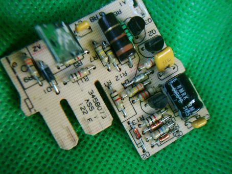
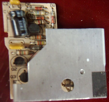
Here’s a picture of the circuit board, heatsink removed –

cuboard

If your courtsey lights don’t go on when either door is opened, the dimmer module may have failed.

Signs that the module has failed are –

The hatch door switches don’t work, but the console hatch switch does.

The interior lights come on by turning the light switch but not when you open the door, or they may stay on all the time.

Test by grounding the thick white wire at the module – door hatch switches should work.

Check the black wire is connected to ground. If so, then dimmer module is not connecting these two wires together and making a circuit when the doors open.

Check that the dimmer is receiving a ground at the yellow wire when either door is open. (This yellow wire may be thin white for some years.)

The dimmer module is no longer available as a replacement part. Also one of the main electronic components is no longer available.

My module was fixed by an electronics expert who examined the circuit and found a suitable replacement part.

Here is all the info I have – I’ve listed most of the parts, in case it can help anyone else.

Location:

The dimmer module is in a small 2"x2"x.5" black plastic box, taped to the wiring loom behind the centre dash. (In my converted to Right Hand Drive vette, the module was midway behind the passenger crash pad.)

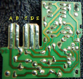
The module is wired –

"A" White wire goes to all of the lamps and supplies negative

"B" Black is Ground. Shorting White to Black will turn the lights on.

"C" Pink/White is 12 volts from the Ctsy/Clk fuse which is hot all of the time.

"D" 2 Yellow wires – (these may be white for some years) come from the Door switches. The switches close when the door is open and provides a ground on the Yellow (or white) wire/wires depending on what door is open.

"E" is the Reset signal used by the Delay Module to turn the Module off when you turn the ignition key to on. So the lights go off.

circuitback

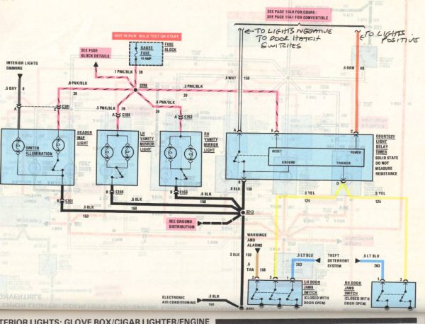
Here’s the circuit diagram in the GM Manual for my 88 Corvette.

timer-circuit-page1

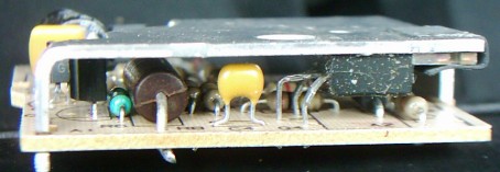
The dimmer module is thin and the circuit is not very complicated –

sideview

topview

The metal piece is a heatsink on a large transistor.

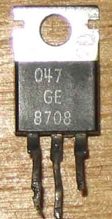
The Transistor is in a TO 220 case, and in mine tested faulty.

to220

It’s no longer available.

Mine was replaced with an MJE 3055 and it worked again!!!!

I suspect that it fails because it takes the most heat/power. The heatsink begins to get warm to the touch within a few seconds.

A test of the amp draw showed my courtesy lights draw 2.8 amps and pressing the rear hatch release increased the draw momentarily to somewhere between 3 and 4 amps.

All parts in the module from my 1988 Coupe look brand new.

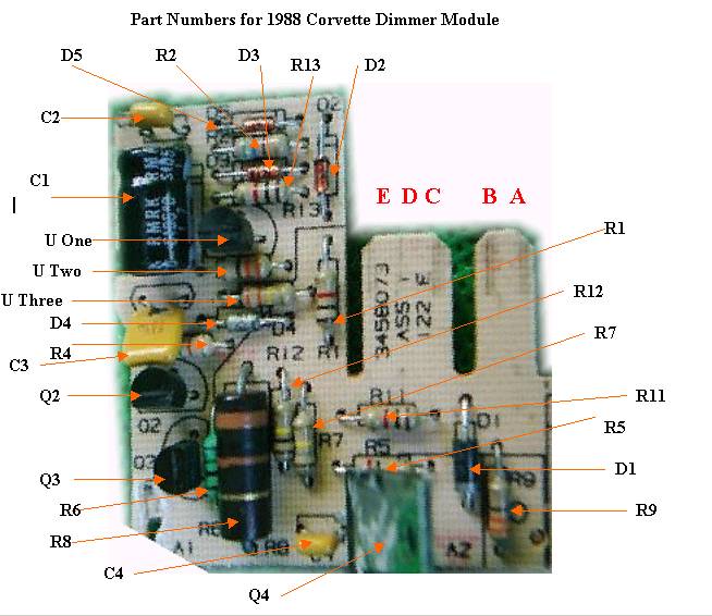
Here’s a parts list – only one signal diode was unreadable.

circuit-board-parts1

3 parts were not given a number so I’ve called them U (Unknown) One, Two, Three

table

Here is a diagram drawn up to work out how the circuit works –

garyscircuitmaster22

A – to Lamps

B – To Battery negative

C – To Battery positive

D – To door switches ( a negative volts signal here will turn lights on, including a 15 seconds delay after low is removed)

E – to positive of dash lights ( a positive voltage signal here will turn lights off)

I hope the information here will help someone else repair their module – mine has been working since August 2005.

back to top

Sun
26
Dec

2004

In January I replaced the old throttle cable and lubricated the cable and throttle body with Lithium spray grease. This made the throttle very smooth, but turned out to be a temporary 12 week fix. The spindle that turns the throttle blades wears an elongated hole in the aluminium throttle body and this jams from the intake of air, even at idle making the throttle stiff.

In February 2004 I had the transmission fully serviced and a Transgo Shift kit fitted which is designed to update the 700R4 transmission and extend it’s life.

Also in February I replaced the stock sealed beam headlights with new Cibie headlights with special extra white globes.

The engine had a full service in March with new Bosch FR7DCX plugs, BP Visco 5000 Oil and VO68 Valvoline filter.

Replaced the Coolant Fan sensor switch in the Aircon line – this switch turns the radiator/condensor fan on when certain conditions are met such as speed under 30mph and aircon on

coolant-fan-switch

May – I fitted new delrin bushes to the left hand pop up headlight.

I Fitted a switch to disable the hatch lights, so the hatch could be left open without draining battery

Reset the mechanical idle and the Throttle position sensor.

Re adjusted the fuel pressure to factory specs.

June – Had brand new radiator fitted as the old one had developed a crack. This made such an enormous difference to the cooling that I had to uprate the thermostat to a 180 degree one as the car was running too cool.

Fitted re-valved Bilstein shock absorbers for a smoother ride.

July – Had the 700R4 auto transmission rebuilt with heavy duty drive shell etc. Work done by the highly recommended Neil Maxwell, at Precise Automatics, Beenleigh.

December – fitted new s/s brake hoses and upgraded bias brake spring.