Find Rob on Google+

‘Tech Tips’

This is not just a blog of routine servicing, but also repairs and improvements

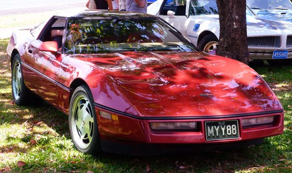
Vette032Web

Between 2012 and 2022 there wasn’t much to report apart from the annual service. I didn’t drive the car very much due to complications from failed back surgeries.

In  2018, for reliability, I replaced the original radiator with a new three core aluminium radiator. The original radiator was still OK but old and only 2 core.

In 2022 I began to hear a rumble from the diff and had it rebuilt by a local expert. Why it began to be noisy is a mystery because I’ve always looked after the car, never driven it harshly. The diff was full of oil of a reasonable colour. My best guess is that it was age combined with not being driven enough. I also had the aircon serviced, fitting a new dryer and evaporator, blocking up several air leaks in the system to make it more efficient and a new valve. I replaced a power window switch. I also replaced all 4 tyres.

Wed
25
Apr

This is not just a blog of routine servicing, but also repairs and improvements

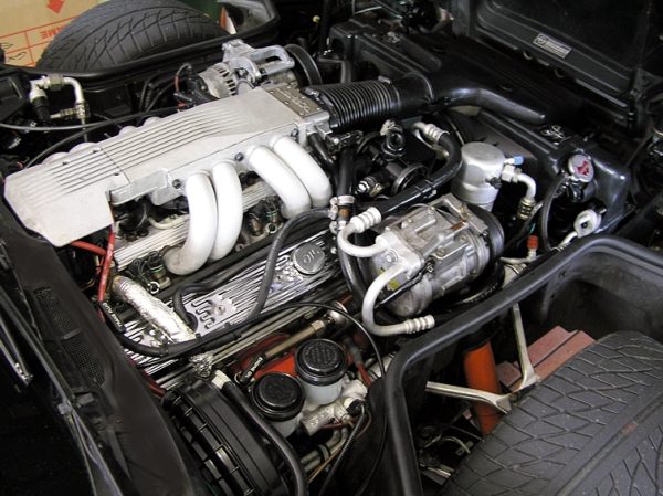
engine-bay00083

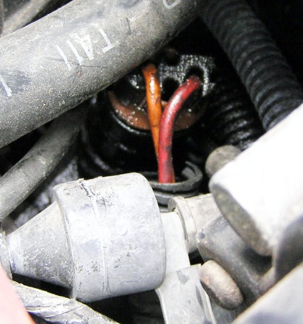
In 2011 there wasn’t much work to do, except that I finally traced the source of a small oil leak at the rear of the engine. The leak suddenly got much worse and it was easy to see that the plastic, electrical, part of the oil pressure sender was coming loose due to oil pressure.

This switch closes contacts above 4psi sending power to the fuel pump. The ECM also powers the fuel pump and this switch is only a backup. I removed the cap, ran the engine and watched the oil rise in the socket- confirming the switch was leaking.

Fitting a new one involved removing the distributor. I made up a list of instructions and it was all about the distributor. There was a single line mentioning the oil pressure switch – “Swap OP switch”

The OP sender is different on different years of C4’s. I took a photo of mine to make sure I got the right part.

I found one in Australia, Eagle Auto Parts Brisbane  Part # PS 167 was identical.


Here are the instructions in case it helps someone else –

Corvette – Replacing the oil pressure switch

Remove Distributor

Bump engine over until rotor points to front.

Disconnect 4 wire plug to dist body and the 2 wires to cap

Undo bolt on RH holding clamp and remove or slide clamp back so dizzy will lift out.

Note that the rotor will turn anti clockwise as dist is removed.

Make visual note –  how much and the  final position.

It’s worth marking the final position in case it gets nudged and for confirmation when replacing


Swap OP switch.


Drop distributor into hole starting with rotor pointing in direction it ended up with when you removed it.

If aligned with the correct tooth ( and you have not turned engine over while it was out ) it should return to the pointing forward  position. Sometimes takes a few goes if you are one tooth out !

Replace 4 wire and 2 wire plugs

TIMING – The ECM expects the dissy to be set at 6 degrees BTDC. To set the timing, the EST wire must be disconnected to stop the ECM adjusting the timing automatically.

There is a plug in the EST wire on LH side of car, near evaporator box –(converted to RH Drive Corvette) unplug it to stop automatic timing control

With the EST disconnected set the engine idling at 1000 rpm.

Don’t adjust the set screw on the throttle body, which has been set v accurately and is a complicated process. Either get someone to hold the throttle or wedge something like a feeler gauge, strips of beer can etc between the throttle and the throttle stop on the throttle body. Any steady rpm from 800-1400 will probably do.

Set the base timing to 6 degrees BTDC

Tighten the distributor clamp.

Reconnect EST plug.

Start engine, check oil pressure on dash.


Routine jobs involved an Oil and filter change, greasing all nipples, rotate the wheels and a general inspection.

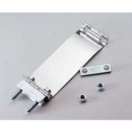
I also fitted a new  82C thermostat and a nifty centre exhaust clamp to replace the standard one where the bolts protruded down and sometimes scraped on speed bumps

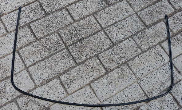
I had a mysterious leak in heavy rain. Water would drip off the interior rear view mirror. I thought it was the weatherstrip and replaced that http://robhealey.com.au/Corvette/tech-tips/windscreenwindshield-weatherstrip-replacement/ Unfortunately the drip was still there.

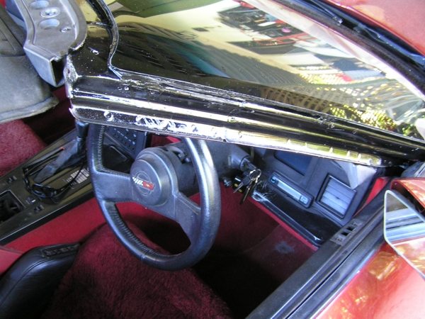
Eventually I found the metal trim to the glass roof was slightly loose on the left hand side. Water was entering there and running along the trim to the front center and then into the car!

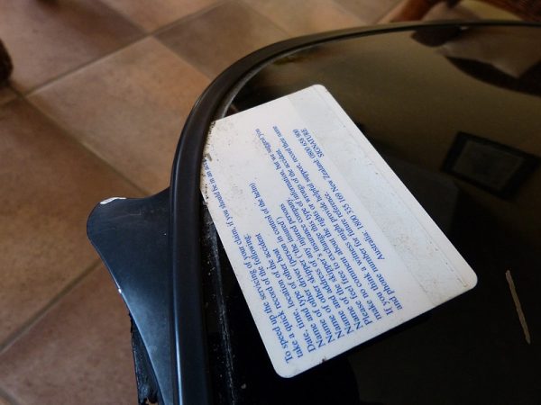
Removing the trim to do a proper repair was not easy.  On the left side it had obviously come loose before, because there was clear silicone in the u channel of the trim. I wedged a credit card between trim and top of glass, lubricated liberally with prepsol and with much force worked it forwards up the left hand side. It came away reluctantly.

The trim had separated along the front to about the middle. After that it was really hard to remove the original factory adhesive.

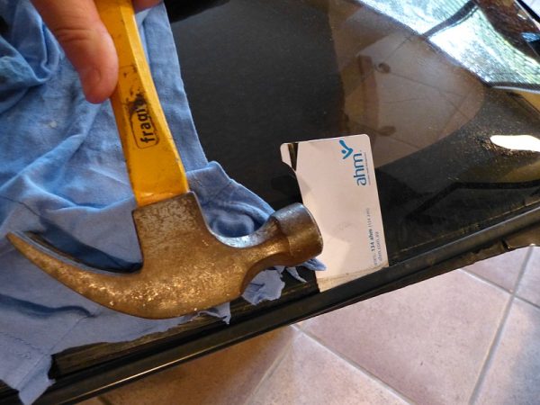
I began again at the rear on the right hand side. This side was extremely hard to unstick. I had to hit the credit card with a hammer to make it move, and it moved just 2 or 3 millimeters each hit!

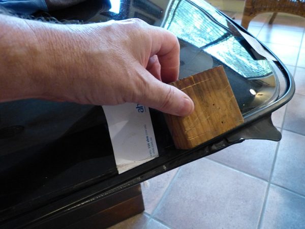
At about the point in the photo above, the card refused to move and I had to hit the metal trim with a wood block, just in front of the card, on the edge where my finger is. I hit it outwards, to drive the trim in the direction you would want to pull it

The pressure from the card and the wood block being just enough to release a little bit more trim from the glue. I had to hit the wood block hard. Kinda scary because a new glass top is very expensive.

On both sides when the trim was off to nearly the corner, I released the trim completely by hitting the rear end of the trim forwards, using a wood block of course.

After a lot of struggle the trim was finally removed, without damage.

I cleaned up the trim first by scraping with a small screwdriver, then 80 grit sandpaper and then wire wool and kerosene. The original adhesive was hard to remove.

NOTE: The trim is very bendy and it is important to support it all while cleaning, to avoid having it kink, which would be very hard to fix.

I cleaned the glass top & bottom by scraping with the tip of a sharp knife, then with 160 grit sandpaper, being careful not to stray past the obvious edge of where the trim sits. I cleaned the edge using a Dremel fitted with sandpaper drum. I got the impression that this edge is the main area that holds the trim onto the ‘glass’.

Once everything was clean I wiped it all down with prepsol, twice. This removes any grease and makes sure the new adhesive will stick.

I used Sikaflex 221 as the new adhesive. At this stage it is very helpful if there are two people, both wearing disposal rubber gloves, with a few clean pairs handy. Also needed is some methylated spirits, I use it in a spray bottle, a roll of paper towel and a cardboard box to throw the paper in when it is covered with excess glue.

Sikaflex 221 has a cure time between 10 mins and an hour. I think the curing time is related to the humidity. I got about 15-20 minutes, which was barely enough, at 65% humidity.

First I laid a bead of Sikaflex in the U channel of the trim. Too much adhesive and the trim will refuse to be pushed on. (You can guess how I know that!)

Then I fitted the trim back on the glass, trying to fit it without sliding it backwards too much, which might create areas with little adhesive.

I cleaned up excess glue by spraying with metho and using paper towels. It is much easier to clean up wet Sikaflex than after it has dried. It’s important not to saturate the glue areas because the Meths can stop the Sika from drying properly, so use just enough.

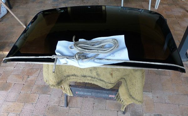
Before the Sika had set I tied a rope under pressure around the rear, holding the two ends of the trim against the glass.

I carefully cleaned up any remaining Sikaflex and left  the roof for  few days. It would probably be OK after 24 hrs but having put a lot of effort into the job, I preferred to leave it as long as possible.

Hope this helps a fellow Corvette owner some day.

Fri
27
May

The left hand door mirror has been rattling for a while. A search of the Corvette Forum soon provided the answer.

It’s an easy fix, but pictures always help.

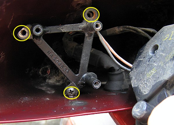
The mirror is held onto the motor by three points – the trunnion which is a mini UJ in the center, the threaded motor rod on the outside and a pivot at the center bottom.

Back of Corvette Door mirror 1988It’s clipped in. With fingers behind the glass mirror it can be gently eased out of it’s clips. I wouldn’t be surprised if the thin trunnion broke, or the clips fractured so it’s worth being very careful. Mine were held in very stiffly but I had no problems.,

The motor is held by 3 screws to a frame and it was the frame that was loose and rattling.

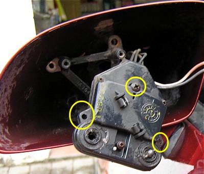
I removed the 3 large screws holding the motor onto the frame- circled in yellow.

Corvette door mirror Motor

Once the motor was removed I could see the 3 screws holding the frame and they were all loose. I removed and cleaned them then retightened them

Corvette Loose Door MirrorPressing the mirror back into it’s clips, especially the top of the trunnion, required more force than I expected. All went back OK and no more rattling noise from a loose door mirror.

1988 Corvette Rear Wheel Bearing replacement –

I got the information from several posts on the the Corvette Forum  http://forums.corvetteforum.com/c4-tech-performance-48/?id=48  ,  from 101 Projects for the Corvette by Richard Newton  and from a friend, Rod, who has done the job himself.(Rod’s comments in italics)

There are plenty of warnings on the Corvette Forum NOT to buy cheap Chinese bearings.

I bought the bearings from Corvette Recycling  http://www.corvetterecycling.com/ in 2009 for us$356

Each side has a steel, teflon coated washer which is important to prevent noises. I found them at Corvette Central, us$35 inc shipping.

Here are my notes to Steve the owner/mechanic at Advanced Automotive Cairns, who looks after my vette really well –

Hi Steve,

Have supplied two new washers (see diagram) these are very important and stop a click noise – they must go the right way round and should fit flush with the hub- note how the old ones are fitted. Please use plenty of anti seize grease on splines and washers.

Some people remove the halfshaft, some leave it in place and get at the torx bolts with a 6″ or 12″ extension- The torx bolts need to be clean and if stuck can be heated carefully.

Taking shaft out makes access easier but more work. Problem is torx bolts are often frozen in and you have a problem getting the right leverage around the shaft.  Spray with WD40 before. Make sure torx bolt heads clean first so no slip.

Note: Steve left the halfshaft in place, but says he needed several extensions to get access and he used a NEW torx bit.

Make sure you wire brush the splines on the yoke clean

PROCEDURE:

1 Remove ABS sensor to prevent damage

2 Undo 2 bolts holding caliper to knuckle ( spindle / upright / whatever you want to call it )  and tie caliper assembly out of the way.

3 remove brake rotor

4 remove cotter pin (36mm) and washer from brake assembly
Hub nut is 36mm; should be tight , very f’ing tight.

5 Mark half shaft so it can be replaced same position

6 Remove UJ straps and drop half shaft
Don’t always work like that. Shaft will not necessarily drop out without removing other suspension parts ( bottom chamber arm ) so knuckle can be levered out to gain clearance room for uni cap to clear side yoke

7. Undo three 55mm torx bolts that hold bearing in

Refit
1 Tighten torx bolts to 66ftlbs

2 Fit new thin Teflon coated washers on splined area of half shaft
Must fit up flush to the inside. If there is a gap they are on backwards
Put a little grease on both sides. Washers should fit directly against the bearing

3 Install halfshaft, leave caps off

4 Place calliper bracket and bearing on rear spindle- lube splines with anti seize grease

5 Install spindle washer and nut

6 Tighten nut to 185-192 Ft/Lbs – get it tight on car and finish when wheels on ground

7 Replace nut retainer and fit

8 Replace brake rotor

9 Install calliper

10 Install abs sensor new cotter pin

Split View Diagram – Teflon Washer arrowed- (NOTE Main nut Torque setting incorrect here)

diagram

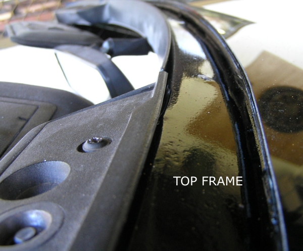
While my old windscreen was removed, I took the opportunity to have the window frame sandblasted back to bare metal and repainted. Then I painted over the new black paint with Xtroll, a heavy duty rust preventative and converter which appears similar to the US POR15.

black-side

It set hard in a few hours and made the black paint look very shiny. I think it will be an excellent rust preventer because it is a thick semi hard coat and the drips were very hard to remove (with Kerosene).

black-top

I had many replies to my post on the Corvette forum about which weatherstip glue to use for the weatherstrip.

The concensus was NOT to glue the weatherstrip. I was surprised, but it makes sense – the side touching the door or hatch can’t be glued and is still watertight, so why does the other side have to be glued. The advantage is that the weatherstrip can be easily removed at any time without damage.

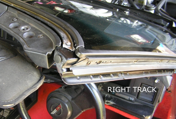
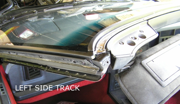
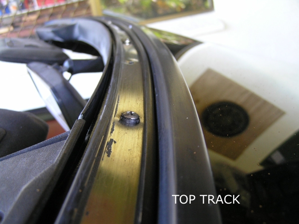
Once the frame was ready I cleaned up the two metal strips that run along the sides and top. The underneath piece is also the black trim around the windscreen and the top metal piece is a track for the weatherstrip. They are held on with about 4 Torx head self tappers each side and about 6 along the top.

right-track

While I had decided not to glue the weatherstrip, I could see there were two possible points of entry for water
1. Between glass and the black metal trim which I think this is called the ‘reveal’
2 Between weathertrip and topside of the black metal trim.

I could glue the whole thing with sikaflex and probably guarantee no leaks but would probably never be able to remove the trim without a lot of damage if I had to replace the windscreen again.
The trims are discontinued so I don’t think this was a good option.

Any glue of lesser quality than sikaflex would let water through in time.

If I used No Glue, at least the water would drain away quickly!!

I decided to use a thin bead of butylmastic, (5 year guarantee- so I guess it will let go in time) between the metal trim and the glass.
I’m hoping that this will stop or slow down water entry.

Theoretically because the butyl mastic stays soft in the centre, it will make it easier to remove the metal trims without damage.

left-track

I soaked all the screws in lanolin and sprayed them with lanolin after inserting.

I stuck 2mm foam under the metal strips where they touch the metal frame, as a second barrier to water ingress at this first layer.

Weatherproofing of the second layer is all up to the rubber weatherstrip.

top-track

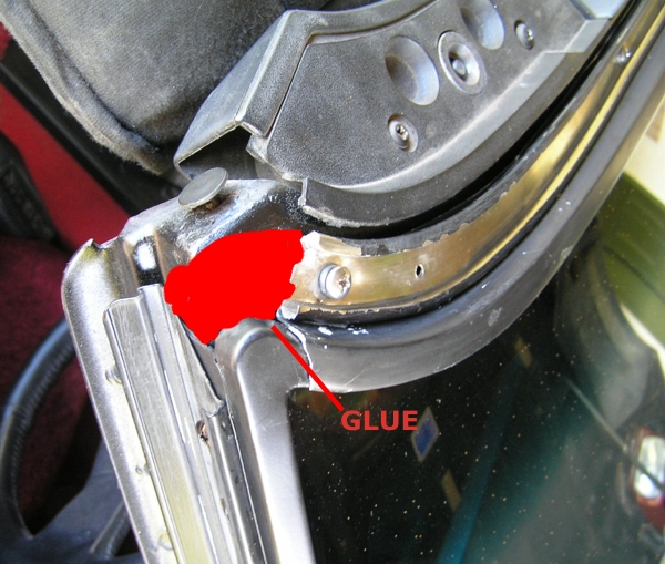
I put some butyl mastic on the two top corners where they leave the side track and go to top track, otherwise it wasn’t glued except for the bottoms which apparently need a drop of glue. I managed to get new Christmas tree plastic plugs (6 needed) from Repco.

top-cnr-glue

From posts I’ve read, there was some possibility that the roof wouldn’t go back on because the new weatherstrip might be too firm, same as the doors being hard to close when the weatherstrip is new. Apparently there is an adjustment under the upper plastic trim, but mine went on with no problem.

After I spent hours cleaning the old tracks, I read that carby cleaner does the job really well, leaving the original paint intact.

I greased up the new weatherstrip with Hydro Seal Silicone O ring grease and it went back into the track easily, starting from one top corner. One thing i should have done was mask the glass because the weatherstrip flopped about on it while i was fitting it, and the greasse was extremely difficult to remove from the glass – but I am assured now how well it will stay on the rubber!

Mon
13
Apr

Aircon – some interesting facts

I live in the tropics so the aircon is very important, I now have constant vent temps of 6.6C to 7.7C while outside road temps show 33C , I’ve learnt a few things while making my aircon efficient,  here’s what I’ve discovered.

My vette was converted to Right Hand Drive and at the same time to R134 gas . It has the C68 climate control.

The first thing I did to maximise the efficiency of the aircon was to disconnect the heater hoses. I have never needed the heater in Cairns.

I was disappointed with the airflow from the blower – I fitted a new blower and it drew less amps than the old blower, but the airflow was EXACTLY the same – about half what’s needed. I have heard that newer Japanese blowers move more air but haven’t found a suitable one yet. Auto electricians tell me I’m looking for more speed, which makes sense.
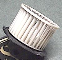
blower3

I took the dash apart – found a beer bottle top, half blocking a disconnected air vent tube, and a few other problems like that. All legacies from the RH Drive conversion. The Air box is moved from RH to LH side during the conversion and also inverted. I cleaned out the evaporator because when new, they have a sheet of foam in front of them and this melts/deteriorates over time, especially in hot climates. I fixed several air leaks from poorly sealed joins etc.

I fitted a dual digital thermometer, from Dick Smith Electronics, so I could measure the centre vent temperature and the cabin temps – and get an accurate view of what was happening.

There is an adjustable inline screw, beside the evaporator box, that sets the low pressure going into the evaporator. In my attempts to get colder air, I turned it down very low, (anticlockwise,1/2 turn) but the evaporator iced up. The signs were the vent temps going from a nice 9 or 10C and rising to past 22C – always fixable by leaving the fan on and turning A/C off so it could thaw out. I turned it the other way (1/2 turn clockwise) and the vent temps were not cold enough- 12 – 13C, and still the evaporator eventually iced up, sometimes after an hours driving.

I also found that when the car was parked and hot, upon restarting, hot air would blow from the vent until the car was moving – the inline coolant fan switch was not working – it should turn the coolant fan on when the aircon is turned on, so that air flows across the accumulator, in front of the radiator. I fitted a manual switch to turn the fan on and this solved that problem until I replaced the switch.
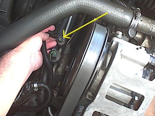
fanon

Arrow points to the switch which is in the gas line running along between the radiator and the front of the engine and

I had the gas checked to make sure the pressure was correct.

The aircon box is in two halves and I found some major leaks on the engine side of the firewall, where the aircon box joins had split open. I also found two oblong section air tubes under the dash, venting air into the dash cavity – if they were a bit longer, that air might have reached the foot well, but the size of the pipe was too extravagant for the amount of moving air. First priority, for me, is to blow cool air on chest and face – then onto feet. So I partially blocked them –I also found the heater door was not completely closed.

After I sealed these significant air leaks, the blower on ‘full’ was now giving maybe 7 out of 10 airflow. I then discovered that this had cured the frozen evaporator problem and stopped it icing up.

By this stage I saw the incredible vent temps of between 6.6 and 7.7C, and no icing up of the evaporator. Aircon mechanics are happy to set the vent temps at 10C so this is a significant achievement. I can only assume that fixing the air leaks and closing the heater door increased the airflow through the evaporator.

When the vette has been parked in the sun, it takes over 30 minutes to cool it down, because the fan doesn’t shift enough air, so I’m still on the lookout for a better fan

Two other things I have discovered are – if the blower only blows full speed, an inline fuse, under the hood, near the bulkhead has blown – I replaced mine with a 15 amp fuse and have had no further trouble.

One day the blower was stuck on, even with the ignition key out – the blower module had failed.
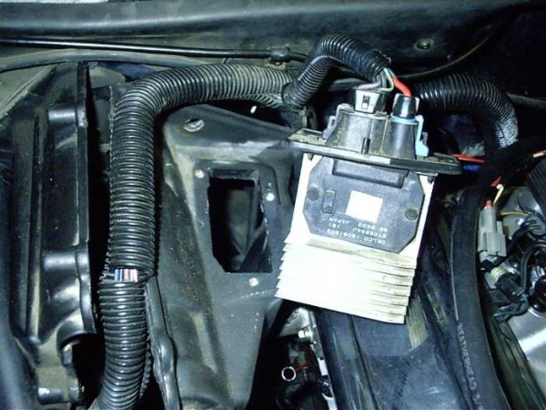
hvaccontrol1

On LH drive cars, the module is on top of the aircon box, so on RH drive cars it’s on the bottom and not so easy to replace, with the chassis close underneath it.

This is the view when laying on the ground looking up at it!!!

p1010006

I got some great help from the Corvette Forum, including two NSW Aussie vette owners – rodj and Aussie Vet .

I’d like to say a very special THANK-YOU to the Corvette GURU on airconditioning, whose username on the Corvette Forum is SunCR. Many many thanks Bill, for your hours of help as we’ve worked through my aircon system .

To sum up – check the gas pressure. Clean the evaporator which probably is clogged with foam that has deteriorated over time, make sure the radiator fan comes on when the aircon is turned on. Make sure the heater door closes properly- that’s VERY IMPORTANT. Look for air leaks. Have the adjustable screw correctly adjusted.
Sat
11
Apr

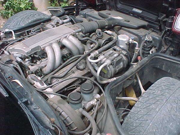
When I first got my Corvette in 2003, the engine was very dirty.

mvc-008s

I did my best to clean it with degreaser and brushes first. I was very unhappy with the result – the black plastic parts looked faded and seemed to have a transparent skin that was peeling off in places – it looked bad.

 I heard about this way of regaining the black on faded parts on the Corvette Forum, this involves spraying a warm engine with Armourall Tyre Spray.

Armor All Tyre Foam

 A few people said it worked so I did a small test area. It made the plastic go black and shiny and it looked so much better. I sprayed everywhere in the engine bay including inside the hood. It made a huge difference and lasts and lasts – I’ve never seen anything revert to the grey white powdery look – I was amazed at how good and easily it fixed everything.

After Using Armor All –

clean-engine10007

Note: As part of the original cleaning up of the engine and maintenance, I also replaced the Rocker covers and shockabsorbers, painted the exhaust manifolds etc. Note the vaccum booster, the AIR diverter box, the inlet manifold hose, top of radiator –  after the spray they came up like new!

I was concerned that everywhere would turn into a gooey sticky mess but that’s not the case – I now spray the wheel wells, under the bonnet – everywhere – remember not to spray on Serpentine belt as it’s slippery.

UPDATE – I’ve been sprucing up the engine compartment with Armorall for a few years now. I can definitely say it does not harm anything, there’s no noticeable build up, it’s not sticky or attracts dust. It’s just a fantastically easy way to keep the engine looking good.

In 2010 before the 7 hour drive to the Charters Towers car show, I sprayed the engine bay, including under the hood which was very faded, with Armor All Tyre Foam. Everything came up like new. The car show is a 2 day event and at the end of day one I noticed grass seed stuck all over the engine bay, the radiator hoses and top of radiator, it looked terrible. They had dried hard and wouldn’t wipe off. I drove the vette back to the motel late in the afternoon and back to the show the next morning. When I lifted the hood EVERYTHING WAS SHINY AGAIN!!!! I assume that when the engine heats up, the Armor All becomes fluid again, or something like that. Those grass seeds had vanished. OK this sounds like a miracle, but it’s true. I have no connection with Armor All, I don’t sell any car products, I’m not in any related industry, just reporting what is happening to me.

Instructions –
Wash engine for the first time application and get everything as clean as you can, spray onto a warm engine, close the hood and wait 20 minutes – TOO EASY – they’re bound to make it illegal !!

Mon
10
Nov

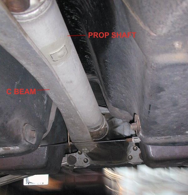
How to replace UJ’s WITHOUT removing C Beam

The factory service manual states that the C Beam must be removed to replace the universal joints on the propellor shaft. Some members of the Corvette Forum said that this was true, BUT a few said it was possible to do it and NOT disturb the C Beam – possibly this only applies to Auto trans like mine?

After some research I got confirmation from forum member rodj and some clear instructions on how to do this. The advantages of not removing the C beam is that it reduces the time of the job, possibly by a few hours! and there is no chance that the C beam will not be put back properly, nuts not tight enough etc because it is a well known PITA to work with due to lack of room – it has to be wrangled in and out and also very hard to get at the front nuts which are above the beam.

c-beam

The first part of this info concentrates on the prop shaft UJ’s, and then scorp508 has given permission for me to host his excellent write up on replacing the halfshaft UJ’s

Below is a copy of my write up for the mechanic who did the job for me, and after that scorp508’s tech tip with photo’s. The mechanic reported that my FAQ sheet was a huge help to him and confirmed that everything was correct.

NOTE – Driveshaft and halfshafts are made from soft aluminium and easily damaged.

All nuts/bolts are Metric.

Factory Manual and Haynes Manual supplied

Hood release under LEFT HAND side of dash,

This fact sheet is compiled from info received from other Corvette owners who have done the U/J replacement job themselves and is vouched for by several owners who have followed these or similar instructions.

The manual says to remove the Driveline Support Beam (C Beam) but this is NOT RECOMMENDED – all reports say this is a tricky job

“The C beam is a PITA to remove if you have never seen one before. You need small hands to get up side of tunnel and hold open ender on top of beam while undoing bolts underneath.Then you have to get it out which is a work of art in itself. Replacement also involves measuring alignement, R/R just for the C beam can take hours.”

The instructions for Driveshaft removal came from Rod in Sydney who has done the job many times and it can come out in as little as 10 mins.

REMOVE DRIVESHAFT FIRST so that brakes can lock diff to allow easy undoing of rear UJ Straps on diff.

Mark the drive shaft so you can install it back in the same position to keep the correct balance.

DRIVE SHAFT REMOVAL –

Hoist Car

Drop exhaust

Undo bolts holding uni to diff,  You may need the diff locked in order to crack the strap bolts loose , you can only really work on one bolt at a time and then need to rotate.

Use a long 1/4 drive ext for better access

MANIPULATE DRIVESHAFT OUT –

Driveshaft will  move foward on the trans yoke allowing you to get rear uni’s caps off the diff yoke. Need trans out of gear and handbrake off so you can rotate yoke to best position to get caps out .

Take rubber hammer, and tap the drive shaft FORWARD into the transmission, angle the drive shaft so its above the handbrake cable that goes horizontally across the car.

Take the rubber hammer, and tap the drive shaft out of the transmission.

DS will slide back beside diff head over handbrake cable enough for the  yoke to come free from trans.

The handbrake cable can be undone if needed, but I don’t recommend it because it’s 20 years old and may be brittle and break. (It’s made to come apart at the clip about in the middle)

May wish to have a catch pan under the rear of the tailshaft to keep transmission fluid from leaking on your shop floor

DS can then be moved foward to clear handbrake cable and down.

Check rear trans seal while you have DS out , cheap insurance against leaks.

Remove old UJ’s and fit Spicer K5 -13 XRHD

HALFSHAFT UJ’S

Below is a link to the excellent write up by scorp508, with clear photo’s for the halfshaft UJ replacement. I found a post by him, after he had done his UJ’s which showed there was one alteration to the way he showed the removal. Instead of undoing the camber strut at the inbord adjustment end, he undid it at the outer end, which prevents the camber from being altered and saves having a rear wheel alignement.

Click
HERE
for a link to scorps write up for the halfshaft UJ’s. (Opens in a new window)

back to top

Mon
10
Apr

C4 Corvette Courtesy Lights Dimmer Module

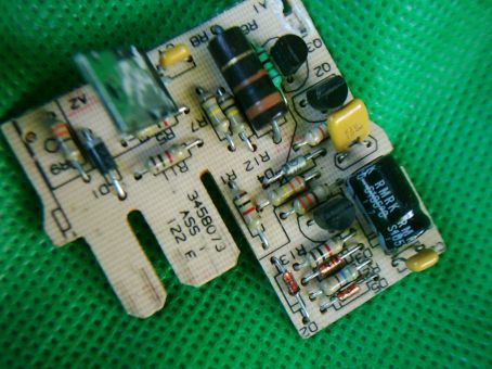
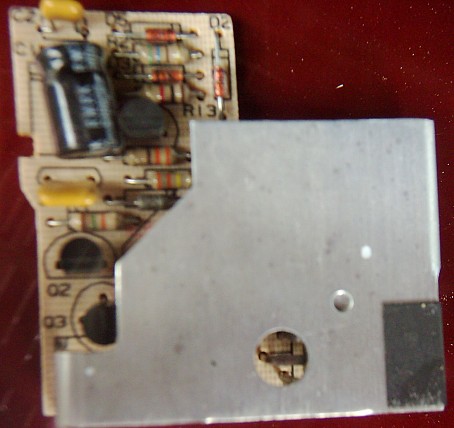
Here’s a picture of the circuit board, heatsink removed –

cuboard

If your courtsey lights don’t go on when either door is opened, the dimmer module may have failed.

Signs that the module has failed are –

The hatch door switches don’t work, but the console hatch switch does.

The interior lights come on by turning the light switch but not when you open the door, or they may stay on all the time.

Test by grounding the thick white wire at the module – door hatch switches should work.

Check the black wire is connected to ground. If so, then dimmer module is not connecting these two wires together and making a circuit when the doors open.

Check that the dimmer is receiving a ground at the yellow wire when either door is open. (This yellow wire may be thin white for some years.)

The dimmer module is no longer available as a replacement part. Also one of the main electronic components is no longer available.

My module was fixed by an electronics expert who examined the circuit and found a suitable replacement part.

Here is all the info I have – I’ve listed most of the parts, in case it can help anyone else.

Location:

The dimmer module is in a small 2"x2"x.5" black plastic box, taped to the wiring loom behind the centre dash. (In my converted to Right Hand Drive vette, the module was midway behind the passenger crash pad.)

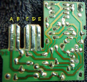
The module is wired –

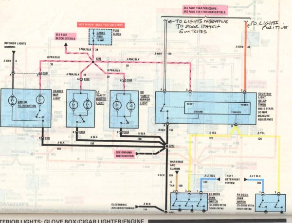
"A" White wire goes to all of the lamps and supplies negative

"B" Black is Ground. Shorting White to Black will turn the lights on.

"C" Pink/White is 12 volts from the Ctsy/Clk fuse which is hot all of the time.

"D" 2 Yellow wires – (these may be white for some years) come from the Door switches. The switches close when the door is open and provides a ground on the Yellow (or white) wire/wires depending on what door is open.

"E" is the Reset signal used by the Delay Module to turn the Module off when you turn the ignition key to on. So the lights go off.

circuitback

Here’s the circuit diagram in the GM Manual for my 88 Corvette.

timer-circuit-page1

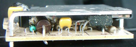
The dimmer module is thin and the circuit is not very complicated –

sideview

topview

The metal piece is a heatsink on a large transistor.

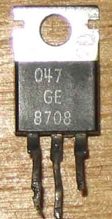
The Transistor is in a TO 220 case, and in mine tested faulty.

to220

It’s no longer available.

Mine was replaced with an MJE 3055 and it worked again!!!!

I suspect that it fails because it takes the most heat/power. The heatsink begins to get warm to the touch within a few seconds.

A test of the amp draw showed my courtesy lights draw 2.8 amps and pressing the rear hatch release increased the draw momentarily to somewhere between 3 and 4 amps.

All parts in the module from my 1988 Coupe look brand new.

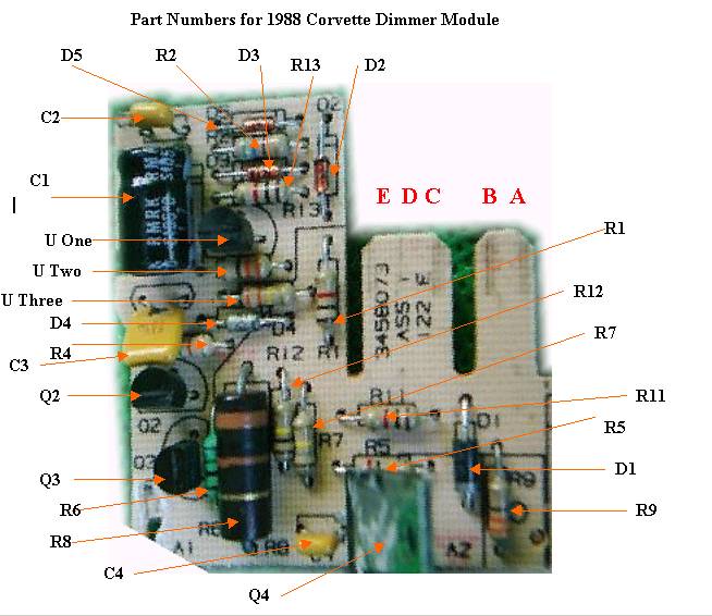
Here’s a parts list – only one signal diode was unreadable.

circuit-board-parts1

3 parts were not given a number so I’ve called them U (Unknown) One, Two, Three

table

Here is a diagram drawn up to work out how the circuit works –

garyscircuitmaster22

A – to Lamps

B – To Battery negative

C – To Battery positive

D – To door switches ( a negative volts signal here will turn lights on, including a 15 seconds delay after low is removed)

E – to positive of dash lights ( a positive voltage signal here will turn lights off)

I hope the information here will help someone else repair their module – mine has been working since August 2005.

back to top